Satisfactory 1.0 · Power Generation & Fluid Systems
Rocket Fuel Power Plant: Exact Blender Ratios & Generator Scaling
On this page
- Rocket Fuel Thermodynamic Profile vs Turbofuel & Nuclear
- The 600 m³/min Pure Oil Cracking Pipeline
- Nitric Acid Synthesis & Nitrogen Gas Pipeline Physics
- Blender Stoichiometry: Solid and Fluid Input Balance
- Fuel Generator Overclock Scaling (250% Clock vs Linear MW)
- Pipeline Hydraulics, Industrial Fluid Buffers & Sloshing Dampers
- Troubleshooting & Power Grid Recovery FAQ
- Satisfactory tools
In Satisfactory 1.0, Rocket Fuel delivers 4,500 MJ/m³ energy density—triple the 1,500 MJ/m³ of standard Fuel and 50% higher than Turbofuel (3,000 MJ/m³). Synthesizing Rocket Fuel in Blenders requires Turbofuel, Nitric Acid, Sulfur, and Compacted Coal (or Nitrogen Gas via the alternate Nitro Rocket Fuel recipe). A single 600 m³/min Pure Crude Oil node converted via Heavy Oil Residue and Diluted Fuel produces enough Rocket Fuel to drive up to 144 standard Fuel Generators generating 36,000 MW, or 57.6 generators overclocked to 250% producing 36,000 MW with vastly reduced factory footprints.
Version boundary: Verified for Satisfactory 1.0.0.6+ (Full Release). Production recipes, MAM Alien Technology research trees, fluid dynamics, power scaling formulas, and dedicated server parameters reflect current stable game code.
Rocket Fuel Thermodynamic Profile vs Turbofuel & Nuclear
Satisfactory 1.0 rebalances mid-to-late-game power generation by establishing Rocket Fuel as the premier hydrocarbon fuel tier before nuclear power. Previously, Turbofuel capped fossil energy generation, requiring sprawling footprints of hundreds of generators. Rocket Fuel dramatically increases energy extraction per cubic meter of crude oil, enabling mega-factories to generate tens of gigawatts of steady power without managing radioactive uranium waste or hazmat logistics.
Compare the volumetric energy densities and generator burn rates across the four liquid fuels supported by Fuel Generators in Satisfactory 1.0:
| Fuel Commodity | Energy Density (MJ/m³) | Burn Time per m³ (Baseline 250 MW) | Generator Consumption Rate (100% Clock) | Generator Consumption Rate (250% Overclock) |
|---|---|---|---|---|
| Biofuel (Liquid) | 750 MJ/m³ | 3.00 seconds | 20.00 m³/min | 50.00 m³/min |
| Fuel (Standard) | 1,500 MJ/m³ | 6.00 seconds | 12.00 m³/min | 30.00 m³/min |
| Turbofuel | 3,000 MJ/m³ | 13.33 seconds | 4.50 m³/min | 11.25 m³/min |
| Rocket Fuel | 3,600 MJ/m³ | 14.40 seconds | 4.1667 m³/min | 10.4167 m³/min |
At a 14.4-second burn cycle (60 ÷ 14.4 = 4.1667 m³/min exact), a single Fuel Generator operating at 100% clock speed (250 MW) turns one saturated Mk.2 Pipeline (600 m³/min) of Rocket Fuel into 144 Fuel-Powered Generators, delivering 36,000 MW of gross generation. Achieving an equivalent 36 GW output on standard Fuel (20 m³/min per 250 MW generator) requires 2,880 m³/min across five separate Mk.2 pipelines.
Open the Satisfactory Production Line Planner → Calculate exact 4.1667 m³/min generator ratios, Nitro vs. Standard Compacted Coal loops, and belt/pipeline caps for any target rate.

The 600 m³/min Pure Oil Cracking Pipeline
Maximizing power output from a single Pure Crude Oil extraction node (pumping 600 m³/min with an overclocked Oil Extractor) requires bypassing the default crude-to-fuel recipe. The baseline recipe yields a meager 400 m³/min of standard fuel from 600 m³/min of crude oil. Instead, utilize the Heavy Oil Residue (HOR) alternate recipe paired with the Diluted Fuel recipe in Blenders.
Execute the oil cracking sequence according to the following factory specifications:
- Stage 1 (Crude Oil Cracking): Route 600 m³/min of Crude Oil into 20 Refineries configured with the alternate recipe Heavy Oil Residue. Each Refinery consumes 30 m³/min of Crude Oil and outputs 40 m³/min of Heavy Oil Residue alongside 30/min Polymer Resin. Twenty Refineries output exactly 800 m³/min of HOR and 600/min Polymer Resin.
- Stage 2 (Resin Disposal / Monetization): Merge the 600/min Polymer Resin onto a Mk.5 conveyor belt. Route this belt directly into an AWESOME Sink to generate continuous coupons, or feed it into 10 Refineries with water to craft 400/min Rubber or Plastic for component manufacturing. Sinking the resin guarantees that polymer backpressure will never stall oil cracking.
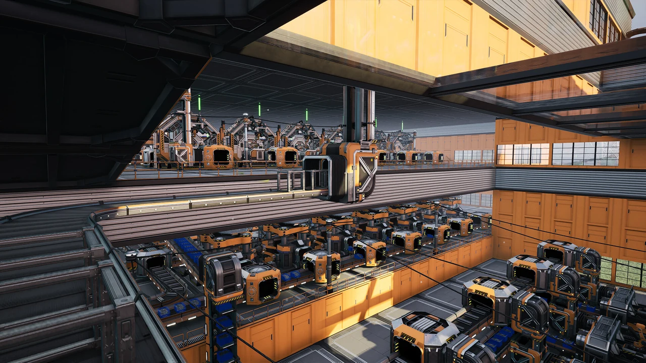
- Stage 3 (Diluted Fuel Blending): Heavy Oil Residue cannot feed Fuel Generators directly; it must be diluted with Water. Route the 800 m³/min of HOR into 8 Blenders running the Diluted Fuel recipe. Each Blender consumes 50 m³/min HOR and 100 m³/min Water to yield 100 m³/min Fuel. The 8 Blenders consume 400 m³/min HOR and 800 m³/min Water, producing 800 m³/min of standard Fuel. Construct a second bank of 8 Blenders to process the remaining 400 m³/min HOR, requiring 1,600 m³/min of Water in total across 16 Blenders to generate 1,600 m³/min of standard Fuel.
This intermediate stage multiplies your liquid volume by 2.66x compared to raw crude oil, providing the necessary hydrocarbon base to drive the downstream Rocket Fuel Blenders.
Nitric Acid Synthesis & Nitrogen Gas Pipeline Physics
Rocket Fuel synthesis requires Nitric Acid, a Tier 7 chemical commodity unlocked alongside the Blender building. Producing Nitric Acid requires three ingredients: Nitrogen Gas, Water, and Iron Plates. Unlike liquids, Nitrogen Gas in Satisfactory exhibits unique pipeline physics:
- Zero Headlift Penalty: Nitrogen Gas exerts zero gravitational headlift downforce. Gas flows vertically through pipelines across any cliff height without requiring Pipeline Pumps. You can pipe Nitrogen Gas from deep valleys straight up to mountain plateaus with zero pump power consumption.
- Pressure Independence: Gases do not slosh backward or suffer from hydraulic wave resonance like heavy liquids. However, gas pipelines still obey maximum throughput caps: Mk.1 Pipelines carry up to 300 m³/min, and Mk.2 Pipelines carry up to 600 m³/min.
To produce 120 m³/min of Nitric Acid (enough for 1,200 m³/min Standard Rocket Fuel), construct 4 Blenders running the default Nitric Acid recipe. Each Blender consumes 120 m³/min Nitrogen Gas, 30 m³/min Water, and 10/min Iron Plates to output 30 m³/min Nitric Acid with zero fluid or solid byproducts. For a single 600 m³/min Standard Rocket Fuel pipe demanding 60 m³/min Nitric Acid, just 2 Nitric Acid Blenders consuming 240 m³/min Nitrogen Gas, 60 m³/min Water, and 20/min Iron Plates satisfy the entire line.
Blender Stoichiometry: Solid and Fluid Input Balance
Satisfactory 1.0 provides two distinct recipes for crafting Rocket Fuel inside the Blender: standard Rocket Fuel and alternate Nitro Rocket Fuel. The alternate Nitro Rocket Fuel recipe skips both Turbofuel Refineries and Nitric Acid synthesis by consuming Fuel, Nitrogen Gas, Sulfur, and Coal directly—at a significantly higher Sulfur/Coal cost and larger Compacted Coal byproduct.
Compare the resource inputs and machine ratios for producing a saturated 600 m³/min Mk.2 Pipeline of Rocket Fuel:
| Recipe Parameter | Standard Rocket Fuel Recipe (with 19/24 Loop) | Alternate Nitro Rocket Fuel Recipe |
|---|---|---|
| Machine Type | Blender (6 machines @ 100 m³/min) | Blender (4 machines @ 150 m³/min) |
| Liquid Hydrocarbon Input | 360 m³/min Turbofuel | 400 m³/min Standard Fuel |
| Secondary Fluid Input | 60 m³/min Nitric Acid | 300 m³/min Nitrogen Gas |
| Primary Solid Input | 90/min Sulfur (via Turbofuel) | 400/min Sulfur |
| Secondary Solid Input | 228/min fresh Compacted Coal (60/min recycled) | 200/min Coal |
| Byproduct Yield | 60/min Compacted Coal (Recirculated to Turbofuel) | 100/min Compacted Coal (Burn in Coal Gens or Sink) |
| Total Output Yield | 600 m³/min Rocket Fuel | 600 m³/min Rocket Fuel |
The alternate Nitro Rocket Fuel recipe dramatically simplifies piping because 4 Blenders eliminate Nitric Acid and Turbofuel steps completely, at the cost of handling 100/min Compacted Coal byproduct per 600 m³/min pipe. Route that byproduct into Coal-Fired Generators or an AWESOME Sink—never let it back up inside the Blenders.
Fuel Generator Overclock Scaling (250% Clock vs Linear MW)
In early access versions of Satisfactory, overclocking power generators imposed non-linear fuel penalties. In Satisfactory 1.0, Coffee Stain Studios standardized power generator scaling: power output and fuel consumption scale strictly linearly. Overclocking a Fuel Generator with Power Shards yields exact 1:1 proportional returns:
- 100% Clock Speed (0 Power Shards): 250 MW generation · Consumes 4.1667 m³/min Rocket Fuel.
- 150% Clock Speed (1 Power Shard): 375 MW generation · Consumes 6.25 m³/min Rocket Fuel.
- 200% Clock Speed (2 Power Shards): 500 MW generation · Consumes 8.3333 m³/min Rocket Fuel.
- 250% Clock Speed (3 Power Shards): 625 MW generation · Consumes 10.4167 m³/min Rocket Fuel.
Feeding a full 600 m³/min Mk.2 Pipeline of Rocket Fuel into baseline generators requires constructing 144 individual Fuel Generators (36,000 MW gross). Each generator occupies a massive footprint, making manifold distribution bulky.
By inserting 3 Power Shards into each Fuel Generator (clocking them to 250%), each unit produces 625 MW while consuming 10.4167 m³/min Rocket Fuel. A 600 m³/min pipeline now feeds exactly 57.6 generators (57 generators at 250% plus 1 generator clocked at 150%). This slashes building counts by 60%, simplifies pipe manifolding, and reduces construction material costs significantly.

Pipeline Hydraulics, Industrial Fluid Buffers & Sloshing Dampers
Rocket Fuel power plants represent the most common site of fluid oscillation failures in Satisfactory. Fuel Generators consume fuel in discrete batch pulses rather than a perfectly smooth continuous draw. Across a manifold of dozens of generators, these batch pulses create harmonic fluid waves (sloshing) inside the pipeline. Liquid sloshes back and forth, causing generators at the far end of the manifold to periodically starve for fuel, triggering intermittent power dips.
Implement the following three engineering safeguards to maintain 100% pipeline stability:
- Elevated Feed Manifold: Construct your main Rocket Fuel supply pipe on elevated pipeline supports at least 4 meters above the generator input ports. Connect each generator via a downward vertical drop pipe. Gravity prevents liquid from sloshing backward up the feed pipe once it enters the generator intake.
- Dual-Ended Loop Manifold: Never terminate a fuel pipeline in a dead-end cap. Connect the far end of the supply pipe back into the beginning of the manifold, forming a closed continuous loop. This balances pressure differentials and ensures generators receive fuel from both directions simultaneously.
- Industrial Fluid Buffers with Check Valves: Install two Industrial Fluid Buffers between your Blender array and the Fuel Generator bank. Place a Valve immediately before each buffer set to allow flow in only one direction. The buffers absorb momentary Blender production pauses, while the valves prevent reverse pressure waves from traveling backward into the Blenders.
Troubleshooting & Power Grid Recovery FAQ
Why do my Fuel Generators oscillate between 95% and 100% efficiency despite a full fuel pipeline?
This oscillation indicates hydraulic backflow wave resonance (sloshing) within your supply manifold. When generators consume fuel in micro-pulses, liquid bounces off the closed end cap of the pipe, creating a reflected pressure wave that temporarily reduces flow below the required 10.4167 m³/min threshold (at 250% clock). To fix this, convert your linear pipe manifold into a closed-loop circuit by connecting the far end back into the main feeder line, and install one-way Valves immediately before each group of 8 generators to eliminate backward fluid reflection.
How do I cold-start a collapsed 36,000 MW Rocket Fuel power plant after a total power grid trip?
A tripped power grid cannot restart if your oil extractors, water pumps, and blenders require power to produce fuel. To perform a safe cold-start, isolate your fuel production wing from the main factory using a Power Switch. Connect a dedicated auxiliary power bank—such as 10 Biomass Burners or a bank of 20 Power Storage batteries charged to 100%—exclusively to your Oil Extractor, Water Extractors, and Rocket Fuel Blenders. Allow the blenders to fill the Industrial Fluid Buffers to 100% capacity. Once fuel pipes are completely pressurized, power on the Fuel Generators, confirm stable 36,000 MW output, and reconnect the main factory switch.
Why is my Nitro Rocket Fuel Blender backing up and shutting down after a few minutes?
In Satisfactory 1.0, each Nitro Rocket Fuel Blender outputs 25/min Compacted Coal byproduct alongside 150 m³/min Rocket Fuel. Across 4 Blenders supplying a 600 m³/min pipe, you generate 100/min Compacted Coal. If that solid conveyor output fills up, the Blender halts liquid output immediately. Route the Compacted Coal belt cleanly into Coal-Fired Generators or an AWESOME Sink with Overflow priority—use our Satisfactory Production Line & Rocket Fuel Planner to check exact byproduct conveyor totals.
Why is liquid Rocket Fuel failing to climb the vertical pipes into my second-floor generator bank?
Liquid Rocket Fuel obeys standard gravitational headlift mechanics (maximum 10 meters vertical rise from machine outputs). If your second-floor generators sit higher than 10 meters above your Blenders, fuel will pool at the base of the pipe and refuse to climb. Install an inline Pipeline Pump Mk.2 on the vertical pipe section. A Mk.2 pump provides 50 meters of vertical headlift, forcing liquid upward. Ensure the pump is oriented with its direction arrow pointing upward and connected directly to active power.
How can I verify whether my Nitrogen Gas supply pipeline is suffering from flow bottlenecks?
Interact with the gas pipeline by pressing E on any pipe segment to open the fluid inspection UI. Check the Current Flow Rate gauge. In a Mk.1 Pipeline, flow cannot exceed 300 m³/min; in a Mk.2 Pipeline, flow cannot exceed 600 m³/min. If your Blenders demand 480 m³/min of Nitrogen Gas and you routed them through a Mk.1 pipe, the pipe is physically choked by 180 m³/min. Upgrade all interconnecting segments, pipe junctions, and wall pass-throughs to Mk.2 Pipelines to restore unthrottled 600 m³/min gas flow.